Digital TSOP lock installation instructions
for DP501/5100 type receivers
(AM29DL323D or equivalent TSOP)
|
Introduction
|
Here are step-by-step instructions for the installation of the digital TSOP lock in your receiver. It is fairly simple and can be done in about 15-30 minutes depending on your skills. For best results, take the time to read this carefully and follow the instructions in the order in which they are written here without burning any steps. First, here is a list of tools and supplies you will need:
Small Phillips screwdriver
Power drill
3/16 inch high-speed drill bit
Tape measure or ruler
Felt pen marker (Sharpie)
Soldering iron w/fine tip & resin-core 60/40 solder
28 gauge solid wire (wrap wire)
Wire stripping tool, small long nose pliers, small cutters, X-Acto knife
Magnifying glass
|
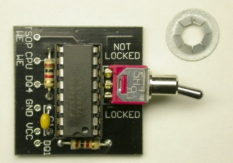
Digital TSOP lock PCB (Printed Circuit Board) shown with special pushnut fastener.
The push nut is required to fasten the board to the back panel on the receiver.
|
1. Drill hole in the back panel of receiver
|
IMPORTANT!:
Before you start, make sure you disconnect the hard drive's IDE and power cables from the mainboard and move them out of the way. Do the same with the power cable that goes to the UHF remote control receiver (the large metal box fastened to the back panel of the receiver case). This is necessary to access to the mainboard's circuitry and will prevent the drill bit from accidentaly getting caught in the UHF remote power cable while drilling the hole.
|
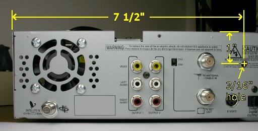
Remove the IRD cover. Use a tape measure or ruler to take measurements and mark the center of the hole to drill with a felt marker. Drill a 3/16" hole 7 1/2 inches from the left-hand side of the receiver case and 1 inch from the top of the receiver case as shown in the picture below.
|
|
TIP:
Turn the receiver upside down and place a small wooden block behind the metal panel while drilling the hole. This will produce a cleaner hole (less burrs on the backside of the hole) and prevent harmful metal chips from going into the receiver. Make sure you clean off any remaining metal particles after drilling since those could cause shorts on the mainboard and seriously damage your receiver.
|
2. Solder wires to PCB
|
Cut 6 lengths of wrap wire. Make each wire 6 inches long. Strip about 1/8" insulation off one end of each wire and solder all the wires to each of the 6 pad/holes on the front edge of the PCB (DQ1, VCC, GND, DQ4, CPU WE, TSOP WE). It is recommended to insert the wires into the bottom side of the board and solder those from the top side. This is not absolutely required, it just makes for a cleaner looking result.
|
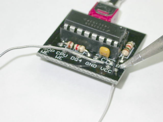
Soldering the wires onto the PCB from the top
|
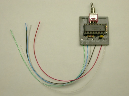
PCB with all wires soldered on and ready to install in the receiver
|
3. Fasten PCB to receiver back panel
|
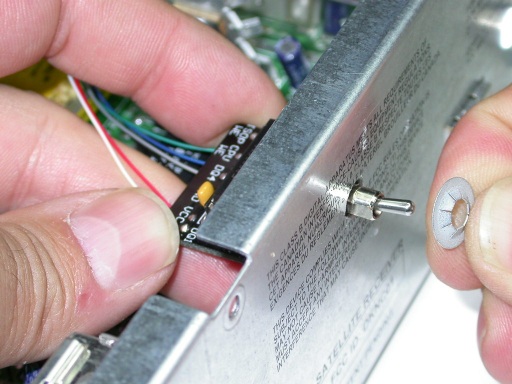
Put the PCB's switch lever through the hole from the inside of the receiver. Hold the PCB firmly against the back panel and slide the pushnut over the switch's bushing from the outside of the back panel. The nut is stiff to insert at first and requires a bit of "finger grease". Once it's started, make sure you push on it straight and even as far back as you can.
One method that works well is to use both index fingers to push the PCB against the inside of the back panel while using both your thumbs to push on the edges of the pushnut.
|
Slide pushnut on
|
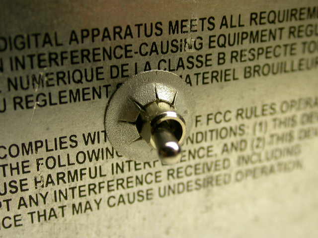
Pushnut fully in
|
NOTE:
You may have noticed that the receiver used in the above picture is NOT a model DP501/5100 but a 2700. Since the fastening of the PCB to the back panel of the receiver is identical for all models, I decided to save myself a little work and re-use the pictures from the 2700 installation docs :-)
|
4. Cut trace on the IRD mainboard
|
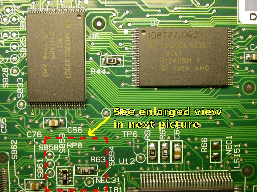
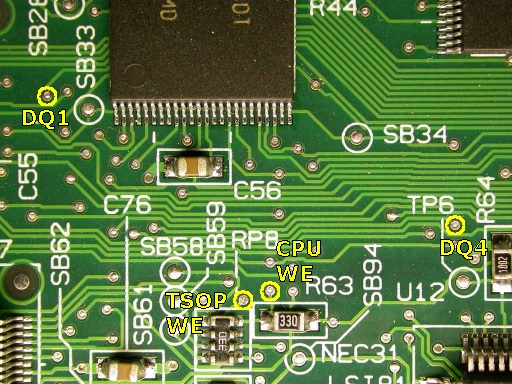
First, use the larger view picture below to locate the area where the trace to cut is located. This is a view of the mainboard when looked at from the back of the receiver. Just below the left-hand side TSOP chip (U6), note the area enclosed in red dashed lines. The next picture shows an enlarged view of that area.
|
|
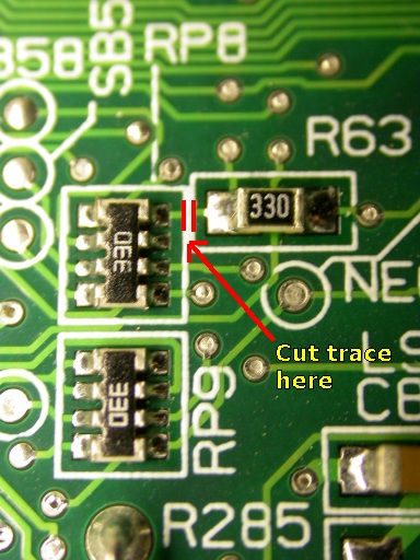
Now cut the copper trace between RP8 and R63 as shown in the picture below. The best way to do this is to make 2 deep scores very close apart across the copper trace using a fine X-Acto knife. Then pry up the small portion of copper in between the 2 scores with the knife blade almost flat to the board. It is recommended to inspect the cut with a magnifying glass to make sure there is no copper left in the gap.
|
|
5. Locate the wire solder points on the IRD mainboard
|
Locate the wire solder points on the mainboard using the pictures below as a guide.
|
Location of solder points 1
|
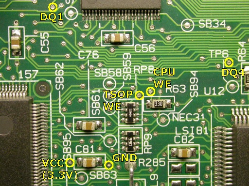
Location of solder points 2
|
6. Solder the wires on the IRD mainboard
|
In order for the digital lock circuit to function reliably, it is essential to keep the wires at minimal length. The 8 inch wires already soldered to the PCB at this point should have a bit of excess length and can be shortened. For an easy way to keep the wire length optimal and a few other soldering tips, please consult the instructions for model 2700 receivers.
Once all the wires are soldered in, the finished result should look like the picture below:
|
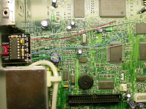
Completed wiring
|
7. Label the TSOP lock switch
|
The final step is to label the lock switch positions on the back panel of the receiver. This is essential in order for the user to be able to tell at a glance whether his TSOP is locked or not. In the picture below, fancy Dymo labels were used but you can simply use a felt pen marker if you want. Just be aware that Sharpie ink markings will come off with alcohol or other solvents. Black pen markings are also harder to read when the receiver is in a dark place (inside a stereo cabinet for example). Printed labels don't have these shortcomings.
|
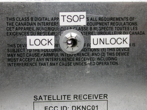
Locked and labeled :-)
|
You're all set. When ECM's come down, you will still get the message "Serious error has occured with your receiver". But the difference is that your TSOP will NOT have been zapped. When that happens, simply pull the card out of the receiver and push it back in. You will be back up and running in a few seconds.
|
Footnote
|
The credit for the logic design of this lock circuit (the schematic) goes to rolesp. However, I designed the PCB layout and came up with the idea of putting the switch directly on the PCB. This board was fully tested and is 100% reliable provided you follow the above instructions to the letter.
|

Tucker
|