Digital TSOP lock & EEPROM lock installation instructions
for 4000/4500 "Grey box" receivers
(AM29F040B + AM29F010B or equivalent TSOP's)
|
Introduction
|
Here are step-by-step instructions for the installation of the digital TSOP lock in your receiver. It is fairly simple and can be done in about 30-45 minutes depending on your skills. For best results, take the time to read this carefully and follow the instructions in the order in which they are written here without burning any steps. First, here is a list of tools and supplies you will need:
2 Digital TSOP Locks (see NOTE below)
Small Phillips screwdriver
Power drill
3/16 inch high-speed drill bit
Tape measure or ruler
Felt pen marker (Sharpie)
Soldering iron w/fine tip & resin-core 60/40 solder
28 gauge solid wire (wrap wire)
SPDT (Single Pole Double Throw) sub-miniature switch
Wire stripping tool, small long nose pliers, small cutters, X-Acto knife
Magnifying glass
|
IMPORTANT!!
Since this document concerns Grey box type receivers, I have included instructions to implement an EEPROM lock at the same time. Remember: Grey box receivers DO NOT HAVE A JTAG interface. If your receiver gets ECM'ed, the ONLY way to fix it is to unsolder the TSOP and/or EEPROM and reprogram it with an expensive chip programmer.
The "shorting a pin to force a stream download" trick DOES NOT WORK anymore since Charlie removed the software refresh from the stream.
TSOP extractions & reflashing can only be performed by a qualified, well-equipped technician and its cost easily exceeds twice the amount of the receiver's net worth. And this is a best-case scenario because it assumes that a good dump for this type of receiver is available which may not be the case at all. In plain terms, this means that if your receiver gets ECM'ed, you're screwed. You have been warned.
|
1. Remove mainboard from receiver chassis
|
Remove the IRD cover (8 screws). You must completely remove the mainboard from the receiver chassis. This is absolutely necessary because there is a trace to cut on the underside of the board. Rely on the picture below to locate the various connectors and mounting screws:
|
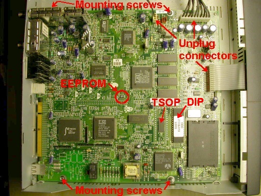
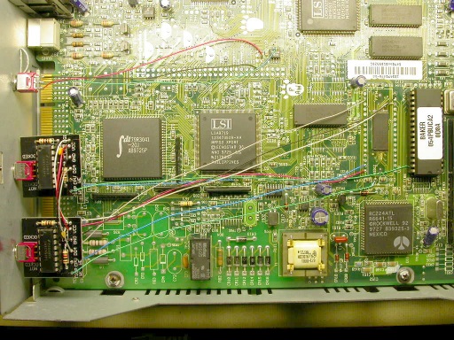
Overview of the receiver mainboard.
Unplug the 4 connectors
Remove the 4 mounting screws (the upper left screw is behind the metal box)
Remove the plastic front panel (press on the plastic latches in all 4 corners)
|
NOTE:
The 4000/4500 receivers are equipped with 2 Flash memory chips which are controlled independently from one another by the system's CPU. The first one on the left-hand side of the picture below is a 32-pin AM29F040B TSOP chip. The second one on the right-hand side of the picture below is a 32-pin AM29F010B DIP chip. The current ECM's in the stream attack BOTH chips.
So in order for your receiver to be adequately protected, this is why you need to install 2 Digital locks instead of only one lock. The 4000/4500 are the only receiver models on which 2 locks are required.
|
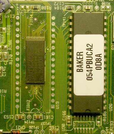
Close-up view of Flash chips AM29F040B TSOP & AM29010B DIP
|
In order to remove the mainboard from the chassis, you must also remove the locknuts from the coaxial connectors and the screw that fastens the RCA connector block onto the backpanel of the receiver.
|
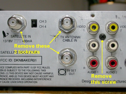
Remove nuts and screw from receiver backpanel.
|
2. Drill holes in the back panel of receiver
|
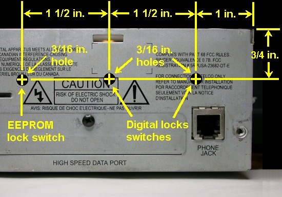
Use a tape measure or ruler to take measurements and mark the center of the holes to drill with a felt marker. Drill 3 3/16" holes. The first is 1 inch from the right-hand side of the receiver case and 3/4 inch from the top. The second is at the same height and 1 1/2 inch to the left of the first hole as shown in the picture below. The third is also at the same height and 1 1/2 inch to the left of the second hole as shown in the picture below
Please note that in some cases, it might be a good idea to drill the left-most hole a tad higher if you intend to use a big DPDT switch for the EEPROM lock. The reason is that there is a metal protrusion in the chassis near that hole. Making the hole farther away from that protrusion will prevent it from getting in the way of the switch later on.
|
|
TIP:
Turn the receiver upside down and place a small wooden block behind the metal panel while drilling the hole. This will produce a cleaner hole (less burrs on the backside of the hole) and prevent harmful metal chips from going into the receiver. Make sure you clean off any remaining metal particles after drilling since those could cause shorts on the mainboard and seriously damage your receiver.
|
3. Cut 2 traces on bottom side of mainboard
|
Note where the DIP-32 pin footprint (U19) around the TSOP is located. Flip the mainboard and locate the 2 traces to cut on the bottom side. Use the picture below as a guide.
|
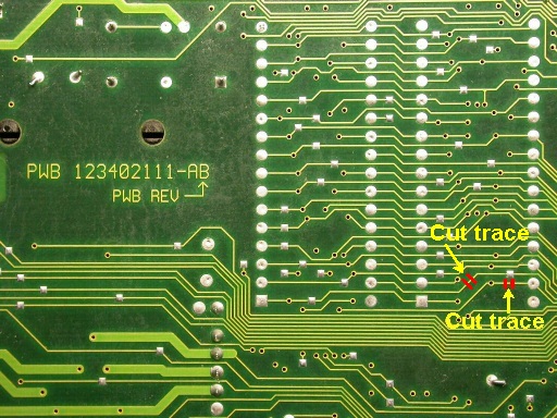
Cut the 2 traces
|
Re-assemble the mainboard into the receiver chassis. Fasten the digital lock board to the back panel using the supplied pushnut. If you don't know how, please refer to the pictures in the 2700 installation guide.
|
4. Solder the 1st digital lock wires to mainboard
|
Use the picture below as a guide to solder the wires from the 1st digital lock board to the proper locations on the mainboard. The location names in RED in the picture correspond to the pads identified by white markings on the near edge of the digital lock PCB.
|
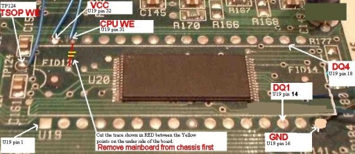
Location of solder points for 1st digital lock wires
|
5. Solder the 2nd digital lock wires to mainboard and 1st lock
|
Use the pictures below as a guide to solder the CPU WE and TSOP WE wires from the 2nd digital lock board to the proper locations on the mainboard. The location names in RED in the picture correspond to the pads identified by white markings on the near edge of the digital lock PCB. Solder the 4 remaining wires of the 2nd lock to the corresponding pad designations of the 1st digital lock (DQ4 to DQ4, GND to GND, etc).
|
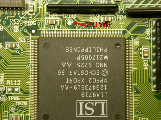
Location of CPU WE solder point for 2nd digital lock wire
|
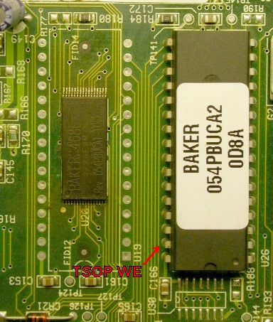
Location of TSOP WE solder point for 2nd digital lock wire
|
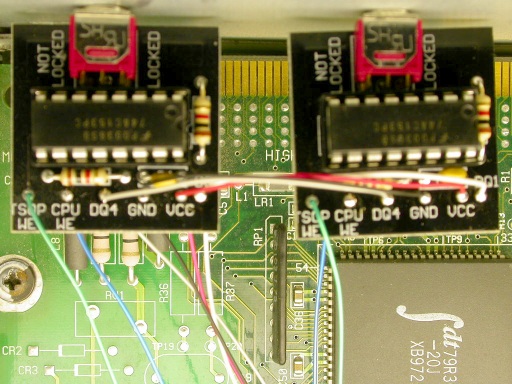
Solder remaining 4 wires of 2nd digital lock (VCC, GND, DQ1 & DQ4)
to corresponding pads on 1st digital lock
|
6. EEPROM lock installation
|
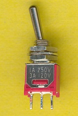
Sub-miniature SPDT switch
|
First, you will need to get a toggle switch. The one shown in the picture on the left is a SPDT sub-miniature type and is ideal for this purpose. If it is difficult for you to find this exact type of switch, you can use a miniature size switch which is slightly bigger but you will have to enlarge the hole in the back of the receiver since those switches have a 1/4 inch diameter threaded bushing. A DPDT (Double Pole Double Throw) switch will also do if you use only one set of contacts.
|
|
A good soldering iron with a fine tip and a steady hand is required for this next step. Heat pin 7 (shown in the picture below) and gently pry it up from the mainboard. Don't try to lift it too high since the pin can break very easily. Then solder a small 28 or 30 gauge wire to that pin. Make sure that both the pin and the wire that's soldered to it does NOT touch the square pad on which the pin used to be soldered. Solder 2 more wires on the VCC and GND contact points shown below.
|
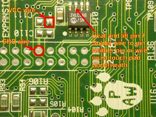
Lift pin 7 of 24LC16 EEPROM and locate solder points for wires
|
Next, mount the switch to the back panel of the receiver in the hole next to the 2 Digital locks (the left-most hole when seen from the back). Then solder the wires to the switch contacts as illustrated in the diagram below:
|
|
NOTE:
The position of the wires on the EEPROM lock switch in the above diagram are such that the Lock and Unlock positions of the switch lever will match with those of the 2 Digital locks. This makes the whole installation more consistent and it makes easier for the user to tell which position is which for all 3 switches.
|
Completed installation
|
7. Label the Digital locks and EEPROM lock switches
|
The final step is to label the lock switch positions on the back panel of the receiver. This is essential in order for the user to be able to tell at a glance whether his TSOP and/or EEPROM is/are locked or not. In the picture below, fancy Dymo labels were used but you can simply use a felt pen marker if you want. Just be aware that Sharpie ink markings will come off with alcohol or other solvents. Black pen markings are also harder to read when the receiver is in a dark place (inside a stereo cabinet for example). Printed labels don't have these shortcomings.
|
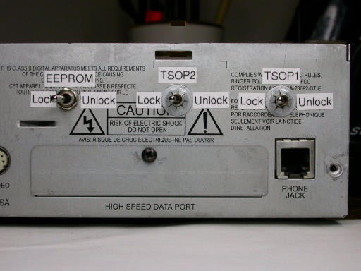
Locked and labeled :-)
|
You're all set. When ECM's come down, you will still get the message "Serious error has occured with your receiver". But the difference is that your TSOP or EEPROM will NOT have been zapped. When that happens, simply pull the card out of the receiver and push it back in. You will be back up and running in a few seconds.
|

Tucker
|